| Module |
Name |
Version |
License |
Source |
Languages |
Platforms |
Type |
Author
|
| ModBus |
ModBus
|
3.11 |
GPL2 |
daq_ModBus.so |
en,uk,ru,de,pt |
x86,x86_64,ARM
|
DAQ |
Roman Savochenko
Maxim Lysenko (2009) — the page initial translation
|
| Description
|
| Provides implementation of the client ModBus service. ModBus/TCP, ModBus/RTU and ModBus/ASCII protocols are supported.
|
| ModBus |
ModBus
|
2.10 |
GPL2 |
daq_ModBus.so |
en,uk,ru,de,pt |
x86,x86_64,ARM
|
Protocol |
Roman Savochenko
Maxim Lysenko (2009) — the page initial translation
|
| Description
|
Provides implementation of the ModBus protocols. ModBus/TCP, ModBus/RTU and ModBus/ASCII protocols are supported.
- Total complexity: > 20 HD[!]
- To Do:
- -
|
ModBus — communication protocol based on the client-server architecture. It was developed by Modicon for using in the programmable logic controllers (PLC). It became the de facto standard in the industry and is widely used for the connection of industrial electronic equipment. Used to transfer data via serial line RS-485, RS-422, RS-232, and network TCP/IP. Currently supported non-profit organization ModBus-IDA.
There are three modes of the protocol: ModBus/RTU, ModBus/ASCII and ModBus/TCP. The first two use the serial communication lines (mostly RS-485, less RS-422/RS-232), the last uses TCP/IP network to transfer data.
The module of the data acquisition provides an opportunity to gather the information from various devices by means of the protocol ModBus in all modes. Also, the module implements the functions of the horizontal redundancy, that is working in conjunction with the remote station of the same level. At the same time, the module of the protocol allows you to create and issue data by means of the protocol ModBus in various modes, and through interfaces that are supported by modules of the subsystem "Transports".
1 General description of the ModBus protocol
Protocol ModBus/{RTU,ASCII} means one lead (requesting) device in the line (master), which can send commands to one or more driven devices (slave), referring to them by a unique address in the line. Syntax of the commands of the protocol allows to address 247 devices on the one connection line of standard RS-485 (less RS-422 or RS-232). In the case of TCP, the addressing excluded from the protocol, as it is implemented in the TCP/IP stack.
Initiative of the exchanging always comes from the leading device. The slave devices listen the line. The master requests (package, the sequence of bytes) in the line and switches into listening the line. The slave device responds to the request, which came to his address.
The end of sending the response is determined by the mode. In the RTU mode, the massage end is determined by the time interval between end of receiving the previous byte and start of receiving the following one — the symbol time. If this interval exceeds the time required to receiving one and a half bytes on a given rate of transmission then receiving the response frame is considered complete. In the ASCII mode, the criterion of the massage end is the character '\r', and in the TCP mode — the expected size of the massage, information about which present in the packet header.
1.1 Addressing
All data operations are tied to zero, each type of the data (register, bit, register of input or bit of input) addresses begin with 0 and ends 65535.
1.2 Standard codes of functions
In the ModBus protocol can be exude multiple sets of commands (Table 1).
Table 1: The subsets of commands of the ModBus protocol
| Subset |
Range of codes
|
| Standard |
1-21
|
| Reserve for advanced features |
22-64
|
| Custom |
65-119
|
| Reserve for own needs |
120-255
|
The data acquisition module uses commands 3 and 6(16) for read and write registers, 1 and 5(16) for read and write bits, 2 and 4 for read bit and register of input, accordingly. For implementation other and atypical commands the module provides a function of the user programming API, which you can call from the template procedure of the logical level, sending arbitrary PDU packages and processing received ones in reply.
The protocol module processes the requests by the commands 3 and 6(16) for reading and writing registers, 1 and 5(15) for reading and writing bits.
2 Module of the protocol implementation
The ModBus protocol module contains the code implementing of the protocol part of ModBus, that is specifics of variants of the protocols ModBus/TCP, ModBus/RTU and ModBus/ASCII. The protocol module in conjunction with the selected transport is actively used by the data acquisition module for implementation the direct queries. Due for the protocol module is independent, using it you can create additional modules for data acquisition by non-standard functions of the ModBus expansion of various automation equipment.
2.1 API of the function of the output requests
API of the function for the output requests (messIO()) operates of exchanging the PDU-blocks, wrapped into the XML-packages, with the following structure:
- <{prt} id="{sId}" reqTm="{reqTm}" node="{node}" reqTry="{reqTry}">{pdu}</{prt}>
- Where:
- prt — name of the tag with the name of the used variant of the protocol (TCP, RTU or ASCII).
- sId — identifier of the source of the query. Used for placing to the output protocol report.
- reqTm — time of the request, that is the time during which the answer is expected, in milliseconds.
- node — number of the destination node or identifier of the ModBus/TCP unit.
- reqTry — number of attempts of repeating the request with the error in the answer. Only for ModBus/RTU and ModBus/ASCII.
- pdu — directly block of the data unit (PDU) of the ModBus protocol.
The resulting pdu replaces the requested pdu in the XML-package, and sets the attribute "err" to the code and text of the error, if it is took place.
2.2 Servicing requests of the ModBus protocol
Input part of servicing of the requests to the protocol module realizes verification and processing of the requests through object nodes provided by the module (Fig.1). Actually, a mechanism is implemented, that allows OpenSCADA to perform the role of the ModBus/TCP server or the slave device of ModBus/{RTU,ASCII}. Thus OpenSCADA gets an opportunity to serve the role of any participant of the ModBus network.
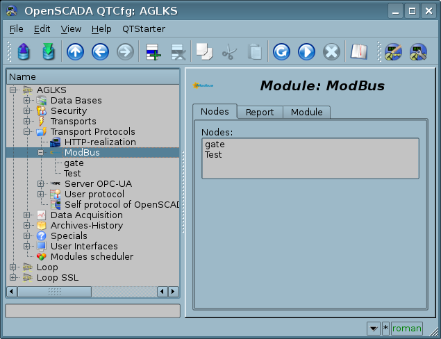
Fig.1. Tab of the list of the nodes servicing input requests of the protocol.
The protocol node is equivalent to the physical node of the device of the ModBus network and can operate in three modes:
- "Data" — mode of reflection of the OpenSCADA data on arrays of registers and bits of ModBus to transfer them at the request of the client node or master.
- "Gateway of the node" — mode of redirecting of the requests to the node of the another ModBus network through this node.
- "Gateway of the network" — mode of redirecting of the requests to any node in another ModBus network, actually carrying out the integration of several ModBus networks into one.
Since the protocol nodes can be created a great number, it turns out that on the one interface, i.e. in the one network, one station on the basis of OpenSCADA can clear provide multiple nodes of the ModBus network with different data.
Consider the specific of the configuration of the protocol node in different modes.
2.2.1 The mode "Data"
The mode is used to reflect the OpenSCADA data on arrays of registers and bits of ModBus. The overall configuration of the node is made in the tab "Node" (Fig.2) by the parameters:
- State of the node, as follows: Status, "Enabled" and the name of the database containing the configuration, with tracking the availability of the data in different storages and providing the sequentially removing duplicates.
- Identifier, name and description of the node.
- The state "Enabled", in which the node must be translated at boot.
- Address of the node in the ModBus network from 1 to 247.
- Input transport, to the network of which the node is belonged to. It is selected from the list of input transports of the subsystem "Transports" of OpenSCADA. Specifying the symbol "*" as the transport makes this node a participant of any ModBus network with the processing of requests from any transport.
- Variant of the ModBus protocol, requests in which must be processed by the node from the list: All, RTU, ASCII, TCP/IP.
- Choice of the mode, in this case the mode "Data".
- Period of calculation of the data in seconds. Specifies the processing period of the data, which forming for the requests, that is: data tables of ModBus, the program of data calculation and servicing of links to the data of OpenSCADA.
- DAQ template or direct procedure language. Provides the selection of a template or language for a direct procedure for the formation and computation of ModBus data tables, as well as for servicing external links to the data model of the subsystem "Data Acquisition".
Node in this mode processes the following standars commands of the ModBus protocol:
- 1 — reading the group of bits;
- 2 — reading the group of input bits;
- 3 — reading the group of registers;
- 4 — reading the group of input registers;
- 5 — setting the single bit;
- 6 — setting the single register;
- 15 — setting the group of bits;
- 16 — setting the group of registers.
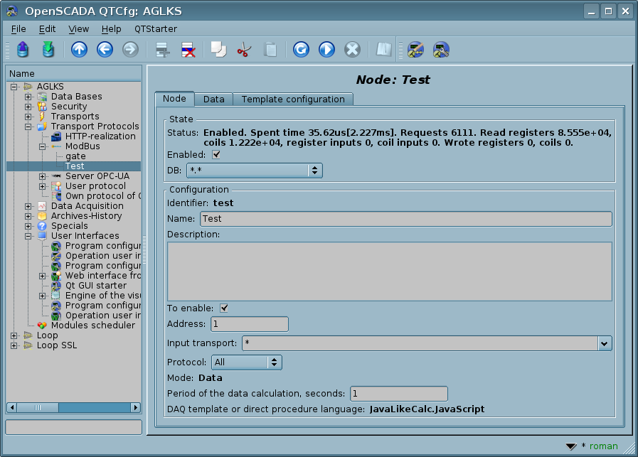
Fig.2. Tab "Node" of the configuration page of a node of the protocol in the "Data" mode.
To form the table of reflection the ModBus network data, that is registers and bits, the tab "Data" is provided (Fig.3). The tab "Data" contains a table of parameters and program of processing the parameters with the specified programming language which is available in OpenSCADA, but in the template there is only the table available and in the "Enabled" mode. The table contains parameters with the properties:
- Identifier — identifier of the parameter. It is the key for formation of the tables of registers and bits of ModBus. Registers and bits of ModBus set as follows:
- R{N}[w~], RI{N}[w~] — specific register and input register form, can be expanded by the suffixes: "i"—Int32, "f"—Float, "d"—Double, "s"—String (by default the size is 10 and up to 100 registers);
- R:{N}[:w~], RI:{N}[:w~] — classic register and input register form, can be expanded by the suffixes: "i4"—Int32, "i8"—Int64, "f"—Float, "d"—Double, "s"—String
- C{N}[w], CI{N}[w], C:{N}[:w], CI:{N}[:w] — coil and input coil.
- Where:
- {N} — ModBus device's data address (decimal, hexadecimal or octal) [0...65535];
- w~e — flags: write mode 'w', registers order inversion '~', register 'e'ndian toggle (to LE in generic and BE for strings).
- Examples:
- "R0x300w" — register access;
- "C100w" — coil access, allowed to write;
- "R_f200", "R_f200~" — get float from registers 200 and 201, 201 and 200;
- "R_i400,300" — get int32 from registers 400 and 300;
- "R_s15,20" — get string, registers block, from register 15 and size 20.
- "R_i8:0x10:w" — get and set int64 into registers [0x10-0x13];
- "R_d:0x20,0x30" — get double float point (8 byte) from registers [0x20,0x30-0x32].
- All other parameters are internal and used for a variety of intermediate calculations, processing, conversion and their values can be operative controlled and changed from the table into execution mode.
- Name — name of the parameter, is used for the naming of the connection.
- Type — type of the parameter from the list: "Real", "Integer", "Boolean" and "String". For the registers and bits of ModBus it makes sense to set the "Integer" and "Boolean" type, respectively. For registers, extended by "f" and "s" prefixes, you must specify the "Real" and "String" types respectively.
- Link — a sign that this parameter should be connected with the parameter attribute of the subsystem "Data acquisition". The links indicated by this sign are set in the "Template configuration" tab.
- Value — original or current value of the parameter, if the node is switched on.
The table by default specifies several parameters of special appointment:
- f_frq — frequency of computing the table by the program;
- f_start — sign of the first computing — the program start up.
- f_stop — sign of the last execution — the program stop down.
 Since an invalid character ',' can be used in the index of extended types of registers, access to it from the program can only be done in an alternative way through the "argument" object:
arguments["R_s10,5w"] = "9876543210";
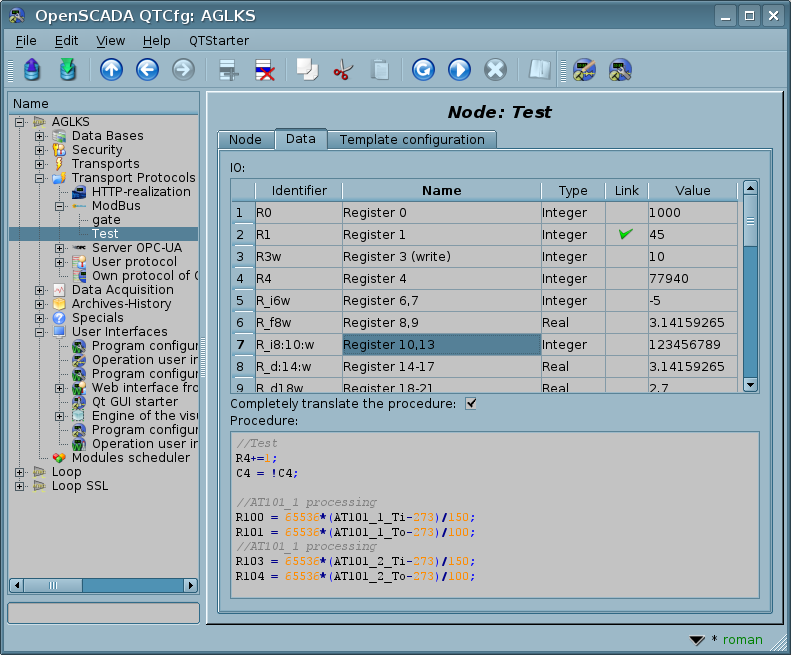
Fig.3. Tab "Data" of the configuration page of a protocol node in the "Data" mode.
For the parameters specified as links, the links can be set for the enabled protocol node and in the "Template configuration" tab (Fig. 4).
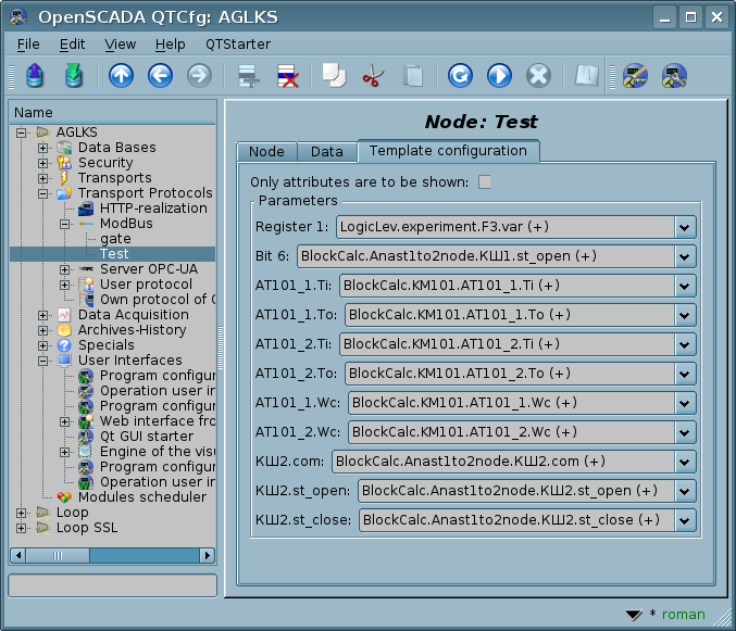
Fig.4. Tab "Template configuration" of the configuration page of a protocol node in the "Data" mode.
2.2.2 The mode "Gateway of the node"
The mode is used to carryover the requests to a separate device in the other ModBus network, from the ModBus network in which this node is configured. The overall configuration of the node is made in the tab "Node"(Fig. 5) by the parameters:
- State of the node, as follows: Status, "Enabled" and the name of the database containing the configuration.
- Identifier, name and description of the node.
- The state "Enabled", in which the node must be translated at boot.
- Address of the node in the ModBus source network, from 1 to 247.
- Input transport, of the network the node is belonged to. It is selected from the list of input transports of the subsystem "Transports" of OpenSCADA. Specifying the symbol "*" as the transport makes this node a participant of any ModBus network with the processing of requests from any transport.
- Variant of the ModBus protocol, requests in which must be processed by the node, from the list: All, RTU, ASCII, TCP/IP.
- The mode choice, in this case the mode "Gateway of the node".
- Transport, in which the request must be redirected, from the list of output transports of the subsystem "Transports".
- Protocol, in which to redirect the request.
- Address of the ModBus network node from 1 to 247, in which the request is forwarded to.
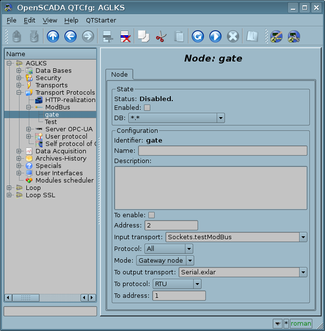
Fig.5. Tab "Node" of the configuration page of a protocol node in the "Gateway of the node" mode.
2.2.3 The mode "Gateway of the network"
The mode is used to carryover the requests of the network at whole to the other ModBus network, from the ModBus network in which this node is configured. I.e. request to the device with any address will be sent to another network, without the readdressing. Overall configuration of the node is made in the tab "Node" (Fig. 6) by the parameters:
- State of the node, as follows: Status, "Enabled" and the name of the database containing the configuration.
- Identifier, name and description of the node.
- The state "Enabled", in which the node must be translated at boot.
- Input transport of the network, from which the requests are transferred. It is selected from the list of input transports of the subsystem "Transports" of OpenSCADA.
- Variant of the ModBus protocol, requests in which must be processed by the node, from the list: All, RTU, ASCII, TCP/IP.
- The mode choice, in this case the mode "Gateway of the network".
- Transport, in which the request must be redirected, from the list of output transports of the subsystem "Transports".
- Protocol, in which to redirect the request.
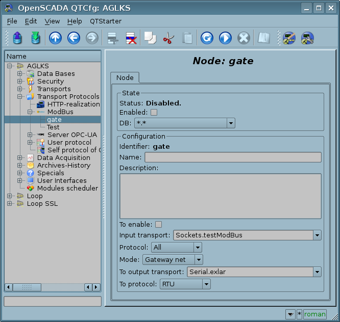
Fig.6. Tab "Node" of the configuration page of a protocol node in the "Gateway of the network" mode.
2.3 Report of the ModBus requests
To monitor and diagnose the correctness of requests for various components, the module provides the ability to enable a report of requests that pass through the protocol module. The report is included by specifying a non-zero number of entries in the "Report" tab of the protocol module page (Fig. 7).
This mechanism is mostly obsolete as its functions are currently performed by the program core:
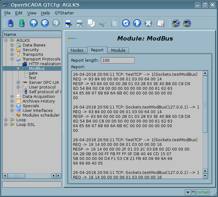
Fig.7. Tab "Report" of the protocol module page.
3 Module of the data acquisition
The data acquisition module provides an opportunity to acquisition and writing registers and bits of devices through protocol modes TCP, RTU, ASCII and commands of request 1 — 6, 15, 16.
3.1 Controller object
To add a data source of ModBus the controller object of OpenSCADA creates and configures. An example of a configuration tab for a controller object of this type is shown in Figure 8.
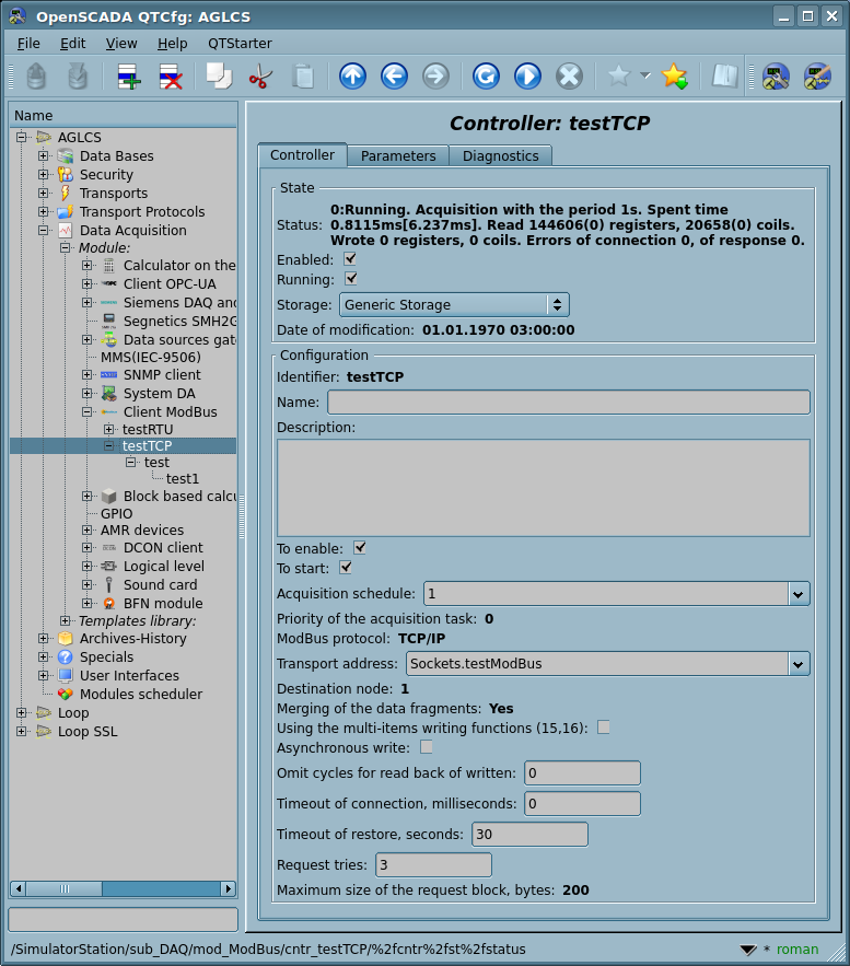
Fig.8. Configuration tab of a controller object.
Using this tab you can set:
- The state of the controller object, as follows: Status, "Enabled", "Running" and the name of the storage containing the configuration.
- Manual restart of the enabled controller object causes the force reformation of the acquisition blocks.
- Identifier, name and description of the controller.
- The state "Enabled" and "Running", in which the controller object must be translated at boot.
- Policy of scheduling and priority of the data acquisition task.
- ModBus protocol, used for requesting the real device (TCP/IP, RTU or ASCII).
- Address of the output transport using the unified connection with navigation. Default port of the ModuBus/TCP is 502. The field may be set to empty and be changed at the runtime. Format of the address is:
- "{TrModule}.[out_]{TrID}[:{TrAddr}]" — typical output with automatic creation TrID at it missing and providing TrAddr;
- "{TrModule}.in_{TrID}:{RemConId}" — initiative input with the connection identifier in RemConId.
- ModBus destination node. In the case of protocols RTU and ASCII this is the unique address of the physical device, and when TCP/IP this is the identifier of the unity.
- Merging of the data fragments. Standard functions 1-4 let to request at once multiple adjacent registers or bits. This strategy often allows to optimize the traffic and time. However, the required registers are not always located adjacent to each other, this option allows you to gather them in blocks of up to 100 registers, or 1600 bits.
- Installing of this parameter must be approached with caution, since not all devices support access to the registers between fragments.
- Using the multi-items writing functions (15, 16). Instead one-item writing will be used the multi-items functions.
- Asynchronous write. Enables asynchronously writing of the changes to the controller, in the general acquisition cycle and after the data acquisition itself, blocking of reading the written values on one cycle (before the writing buffer clearing).
- This mode also prevents for loss the writing data at the connection loss and the wrote data will be transmitted just the connection will be restored.
- Omit cycles for read back of written. Can be useful for PLC which applying the changes not fast and they are processed in some significant time depending on the PLC load. So, the cycles value then specifies count of the omitting read cycles before reading back the changed value, preventing the value twinkle.
- Timeout of connection in milliseconds. Specifies the time interval during which the answer is expected. If there is zero waiting time the transport waiting time by default is used. Allows taking into account individual properties of the controller in the common network.
- Timeout of restore in seconds. Specifies the time interval after which the re-attempt of the request to previously inaccessible device is done.
- Request tries for the protocols RTU and ASCII. Indicates the number of attempts by the repetition of the request in case of incomplete or damaged answer.
- Maximum size of the request block in bytes, useful for controllers with such limits.
3.2 Parameters
The data acquisition module provides two types of parameter: "Standard (Prm)" and "Logical (PrmL)". Additional configuration fields of the parameters of this module are:
- Standard (Prm):
- Attributes list — contains a structured list of configuration for the attributes ModBUS.
- Logical (PrmL):
- Parameter template — address of the DAQ-parameter template.
3.2.1 Standard (Prm)
Main page of configuration parameters of the standard type is shown in Figure 9.
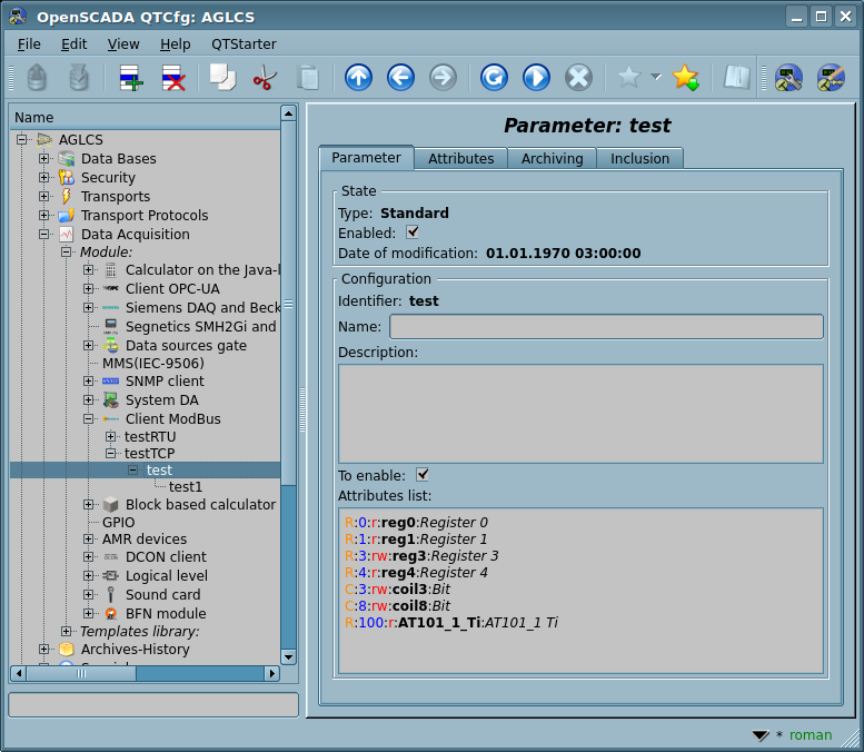
Fig.9. Configuration tab of the standard parameter type.
One attribute line in the parameter of the attributes list can be written as "{dt}:{numb}[:{flg}[:{id}[:{name}]]]".
Where:
- dt — Modbus data type ("R"—register[3,6(16)], "C"—coil[1,5(15)], "RI" — input register[4], "CI"—input coil[2]);
- "R" and "RI" can be expanded by the suffixes: "i2"—Int16, "i4"—Int32, "i8"—Int64, "u2"—UInt16, "u4"—UInt32, "f"—Float, "d"—Double, "b5"—Bit5, "b"—Bit in address, "s[CHARSET]"—String (size by default is 10 and up to 100 registers);
- numb — ModBus data address of the device (decimal, hexadecimal or octal) [0...65535];
- flg — flags: read/write mode (r-read, w-write), strict requesting mode (not combining) 's', registers order inversion '~', register 'e'ndian toggle (to LE in generic and BE for strings);
- id — identifier of the created attribute;
- name — name of the created attribute.
Examples:
- "R:0x300:rw:var:Variable" — register access;
- "C:100:rw:var1:Variable 1" — coil access;
- "R_f:200:r:float:Float", "R_f:200:r~:float:Float" — get float from registers 200 and 201, 201 and 200;
- "R_i4:400,300:r:int32:Int32" — get int32 from registers 400 and 300;
- "R_b10:25:r:rBit:Reg bit", "R_b:25.10:r:rBit:Reg bit" — get bit 10 from register 25;
- "R_s:15,20:r:str:Reg blk" — get string (registers block) from register 15 and size 20."
Line starting with the '#' character is considered as a comment and it is not processed.
In accordance with the specified attributes list, the acquisition and creation of attributes of the parameter are performed (Fig. 10).
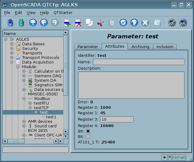
Fig.10. The attributes tab of the standard parameter type.
3.2.2 Logical (PrmL)
Main page of configuration parameters of the logical type is shown in Figure 11.
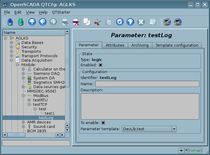
Рис.11. Configuration tab of the logical parameter type.
Link value, when configuring the template (Fig.12), is written in the form {dt}:{numb}[:{flg}].
Where:
- dt — ModBus data type ("R"—register[3,6(16)], "C"—coil[1,5(15)], "RI"—input register[4], "CI"—input coil[2]);
- "R" and "RI" can be expanded by the suffixes: "i2"—Int16, "i4"—Int32, "i8"—Int64, "u2"—UInt16, "u4"—UInt32, "f"—Float, "d"—Double, "b5"—Bit5, "b"—Bit in address, "s[CHARSET]"—String (size by default is 10 and up to 100 registers);
- numb — ModBus data address of the device (decimal, hexadecimal or octal) [0...65535];
- flg — flags: read/write mode (r-read; w-write), registers order inversion '~', register 'e'ndian toggle (to LE in generic and BE for strings).
Examples:
- "R:0x300:rw" — register access;
- "C:100:rw" — coil access;
- "R_f:200:r", "R_f:200:r~" — get float from registers 200 and 201, 201 and 200;
- "R_i4:400,300:r" — get int32 from registers 400 and 300;
- "R_b10:25:r", "R_b:25.10:r" — get bit 10 from register 25;
- "R_s:15,20:r" — get string (registers block) from register 15 and size 20.
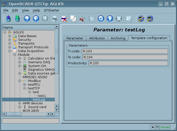
Рис.12. Tab "Template configuration" of the logical parameter type.
The module provides a special processing of a number of attributes of the template:
- f_frq — frequency of the calculation of the template procedure or the time after the last calculation (negative in seconds) for planning by CRON, read-only.
- f_start — sign of the first execution of the template procedure — start-up, read-only.
- f_stop — sign of the last execution of the template procedure — stop, read only.
- f_err — parameter error, full access. The value of this attribute of the template falls into the error attribute of the parameter "err". Write here EVAL for the possibility of setting the attribute "err" from the outside and all others in the Read Only mode.
- SHIFR — code of the parameter, read-only.
- NAME — name of the parameter, read-only.
- DESCR — description of the parameter, read-only.
- this — object of the parameter, allows access to the attributes of the parameter, for example, to access archives-history.
In accordance with the template, underlying the parameter, we obtain a set of attributes of the parameter (Fig. 13).
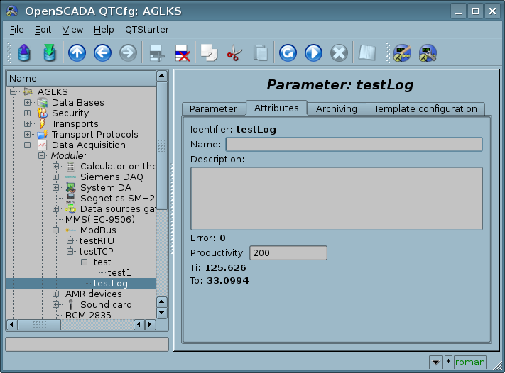
Fig.13. Tab of attributes of the logical parameter type.
3.3 User programming API
Due to the support of the logical type parameters, it makes sense to provide a number of functions of the user API for calling them from the template of the logical parameter.
The object "Controller" [this.cntr()]
- string messIO(string pdu) — sends pdu through the transport of the controller object by means of the ModBus protocol. PDU query result is placed instead of the query pdu, and the error returned by the function.
- ElTp value( string addr, ElTp setVl = NULL ) — direct accessing a value-registers with registering for acquisition.
- addr — the value-registers address in the standard format;
- setVl — setting value, NULL (not specified) only for getting.
4 Links


